Industrial Tools
Torque Systems

Frequently asked questions about torque wrenches, centerline, standard values, calibration...

Why does...? How Do...? What is...? If we...?


This column is where we address some frequently asked questions (FAQ) related to torque and torque controlled tightening. If you have a question that does not appear here, please do not hesitate to contact us.


r team will help you gladly.

Twin Blade Technology improves the capacity of impulse wrenches
Twin Blade Technology

Yokota‘s patented twin-blade impulse mechanism is equipped with two blades which separate the oil cylinder into two opposing oil chambers. The oil pressure affects both blades simultaneously. This gives a steady high impulse leading to a high torque on the joint.


The impulse mechanism delivers one impulse per revolution (cf. ill. 1–8). During phases 1–3 and 5–7 the oil can flow unhindered and no oil pressure build-up occurs. The same applies to phase 4 (B). Even here no oil pressure build-up occurs because the sealing faces cut on shaft and cylinder. Only in phase 8 (A) the sealing faces are sealing and oil pressure build-up occurs. The duration of oil pressure build-up and thereby the duration of the impulse is very short.


The impulse is transferred by the blades to the main shaft and this affects an increase of torque on the joint. Between the primary compression chamber with its high oil pressure and the secondary low-pressure chamber there is integrated a „bypass“ with an adjusting valve. During impulse oil flows from the high-pressure chamber to the low-pressure chamber. By alterating the cross-section of this valve the performance (torque) of the wrench can be adjusted. The impulse sequence is about 10–40 impulses per second. The force transmission by means of oil reduces the noise level as well as vibration.

Torque -- From Tightening Torque over Pretensioning Force to Clamping Force

The operational principle of a bolted joint exists in the compression of several construction units or components. Three quality-determining characteristics will interaction.


Torque means the physical force which affects over a defined lever right-angled on an axis of rotation (vertical rotation acceleration). The torque is measured in Newtonmeter (Nm = kg m²/s²) and is the cross product of lever arm of force times force.


Georgia State University says this about torque: "Note that the torque is maximum when the angle is 90 degrees. A practical way to calculate the magnitude of the torque is to first determine the lever arm and then multiply it times the applied force. The lever arm is the perpendicular distance from the axis of rotation to the line of action of the force."


Apply the same force to a different length lever arm and the torque output changes. The length of the lever arm includes the area on the head up to the center of the fastener.


By interaction with the screw thread the initial tension strength is produced. The pre-loading is the physical force, which is to hold the construction units together. It affects along the screw axis toward the construction units to be connected. Therefore the preload is the force that is supposed to hold the components together. From this the clamping force finally results, which compresses the components to be bolted on to each other and which during load are to behave as one component afterwords. The friction (static friction, self-locking) prevents the bolted connection from loosening automatically.


However, many interfering factors may affect the firmness of the bolt connection, e.g.

  • Frictional loss
  • Setting loss
  • Component failure
  • Constructional fault
  • Manufacturing error
  • Tool failure
  • Faulty handling
  • etc.

Impulse Tools -- a step into future


The Toyota Production System (TPS) worldwide qualifies as benchmark for highly efficient assembly in most different branches of industry. Toyota successfully relies on impulse technology for years. Electronic controlled impulse wrenches of the Japanese specialist Yokota are not the tools for bolted joints of the future – they are the tools of today functioning like they should.


Whoever has watched the development of manual pneumatic nutrunners in the past decades, especially in the automobile and subcontractor industry, can realise a clear line from formerly used impact wrenches over shut-off tools right up to modern impulse wrenches. The advantages of conventional nutrunners – fast, lightweight and nearly reaction-free – had to be accepted with high noise level, vibrations, large torque tolerances plus the impossibility to measure tightening torque. The aggravation of statutory provisions, the manufacturer liability and the wish to use as small bolts as possible, which can be used up to yield strength, have made the application of impact wrenches more and more problematic. Further problems caused by the so-called re-torque shall be ignored at this point.


Later on increasingly used nutrunners with shut-off automatism accrued the advantages that torque was presettable in closer tolerances, that torque was measurable and documentable by transducers and electronic sensors, and that the noise level was considerably lower. Certainly it is useful for manufacturing when the tools stopp automatically at accurate torque and required clamp force, because the risk on human errors is reduced by automatic shut-off. The price to be payed for this advantage consisted of prolonged bolting times. Namely by lower speed of rotation, heavy weight and large dimensions, that generally necessitated two-hand operation due to the reaction of the tool on the operator at the instant of shut-off.


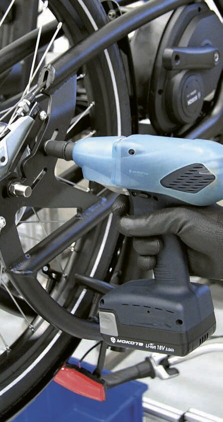
A solution for all these problems was promised then later on by the impulse wrenches increasingly coming onto the market. Beneath the high operation speed they also provide the control of torque. The tool itself is small, leightweight and applicable for one-hand operation. A further advantage is the reaction-freeness of the Yokota impulse wrench. Tissue disease like RSI will be avoided in comparison with other pneumatic nutrunners. Using Yokota impulse wrenches reduces afflictions of the operators and the corresponding financial risks to a minimum.

Primarily on mid-range torque values mainly applied in the automobile industry, the advantages of impulse wrenches are significant:

  • Low noise level
  • Low vibration
  • High torque repeatability at high bolt speed
  • Reaction-free

Because of the strong supporting moments with the angle nut runners these were replaced in the automobile industry nearly completely by other tightening systems. American and European manufacturers developed torque angle of rotation nutrunners with shut-off or with computer-control. The Japanese industry rated such tightening systems as unsuitable because of the high price, the large weight and the too high accuracy (!). The tightening time however is of far higher priority for the Japanese industry. Impulse nutrunners, with or without electronic control, in their understanding would by far fulfill the accuracy requirements. Moreover, such a system must be reasonably related to the quality of the screws and parts. It hardly makes sense to use highly exact screwing systems if the screws themselves have far larger tolerances and thus the completely outweighing portion of inaccuracies to cause. Regarding in the automobile industry occurring safety-relevant screw connections (A-joints), it is of crucially higher importance to record a 100% documentation of all safety-relevant screw connections in writing and/or dataelectronically for each mounted vehicle.


Computer-Controlled Impulse Tools


A prejudice, that is still widespread in the French and in the German automobile industry, exists in the opinion that the torque of an impulse nutrunner is not measurable with the torque measuring systems offered on the market, because they obviously were all voted on screwdrivers and angle nutrunners. Although it is outdated long, this before times correct argument also today is still stated by many users against the use of impulse nutrunners – particularly with safety-relevant screw connections. This opinion in practice however is verifiably disproved the measuring systems offered by Yokota as well as when using the recent test systems of the British measuring technique specialist Crane.


The problem was solved by the computer-controlled system nutrunner developed by the company Yokota – a system, which is based on torsion of the drive shaft, and conducting a group counting. For measuring the torque the Yokota system nutrunner uses a sensor in the pulse mechanism, which by means of strain gauge transforms the torsion of the drive shaft into electrical signals, which are then transmitted to the control unit. Torque and pulse number can be controlled, checked and printed out or exported to the computer with the YETC. The electronically controlled hydraulic impulse nut runner works with a very high number of impulses. Thus further advantages result:

  • A screwing procedure transacted with a system nut runner requires approx. 2 seconds and can be implemented with one hand also still at a tightening torque of 600 Nm.
  • Computer-controlled tightening systems offer short screwing times at low costs.

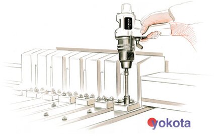
For the Japanese automobile industry it is characteristic that relatively simple however fast performing tools are used for assembly. The best proof for it is that the Japanese automobile industry in strong measure applies impulse nutrunners and screwing systems of Yokota.


Re-torque Angle of Rotation


In the automobile industry numerous torque wrenches are in use, which are used to "re-torque" bolt connections accurately on the demanded torque value. This processing step can be saved by a system nutrunner. Routine controlling of the bolt connections tightened with system nutrunners is randomly made with torque measuring wrenches. In the same way this is handled when using torque angle of rotation nutrunners. This approach to examine bolt connections from handheld screwing systems was generally usual and appreciative practice in the automobile industry. A meaningful relation between the torque accuracy and the firmness of a bolt connection however can only be made by determination of the apparent yielding point of a screw. This is technically possible, execution conditionally however high work expended and is therefore very cost-intensive. A further reason for the grasp to the Yokota impulse nutrunner is thus the maximum clamping force with minimum loosening risk.


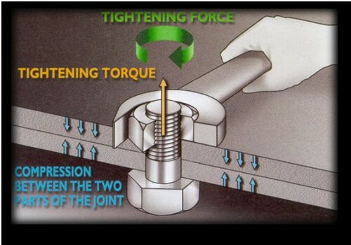
With bolt connections clamping is most important – thus the axial tension in the pin, which ensures the cohesion of the parts. The way to the correct clamping force leads across the attitude of the starting torque after the characteristic values of the screw. In practice it shows up that after tightening rather high setting losses arise. Often this reduces in the long run the tension desired substantially. The experience shows, and lab tests confirm this, that the setting losses are substantially larger with a screw tightened with a angle nutrunner than after the use of an impulse nutrunner. Reason for it is that with the application of an impulse nutrunner while tightening the screw itself is shifted into a condition of vibration. Setting takes place here to a large extent already during bolting. In addition, with handheld tools the application of the angle of rotation is afflicted with many uncertainties.


Yokota differently solves the problem of pulling tight by a certain angle of rotation. Pulling tight takes place via some additional impulses after reaching the adjusted torque, the so-called afterpulses. Additionally between one to fifteen impulses can take place. Beside the vibration when tightening setting losses are compensated to a large extent when tightening by this afterpulsing. Hereby a substantial demand of the automobile industry is fulfilled. Moreover there is the possibility of hundred percent control and documentation. In addition optical and acoustic warning signals can be integrated separately into the system or together and it is possible to define so-called bolt groups. For example twelve screws can be defined as a group. If with tightening a bolt is forgotten then, the system refuses the transition to the next group of screws.


Recommendation


Only a 100 % documentation of all screw connections offers demanded security. All torque values must be traceable; only like that it is ensured that each screw was tightened. This means that impulse nutrunners should be used in the automobile industry in accordance with following recommendation:


  • VDI 2862 category C: Standard impulse nutrunner with high torque repeatability
  • VDI 2862 category B: Shut-off impulse nutrunner or Poka Yoke nutrunner
  • VDI 2862 category A: Computer-controlled system impulse nutrunners

A meaningful and appropriate relation is ensured in this way between accuracy, screwing time and conditions of work for the operator. Yokota used up itself the continuous technical advancement, the observation of the production processes, the efficiency improvement as well as the increase of speed and security - for the advantage and benefit of the automobile industry.

Torque Application Tools according DIN EN ISO 6789

Denominated as „torque wrenches“ are manually operated tightening tools by which a defined tightening force (torque) can be applied to joint elements like bolts or nuts. Torque is a force exerted at a distance from the axis of rotation. Change either the distance from the axis of rotation or change the amount of force that is exerted and the torque changes.


According to DIN EN ISO 6789 torque tightening tools are differed into indicating (type I) or releasing (type II) models.


Type I indicates the torque value by a mechanical scale, a dial gauge or an electronic display (“measuring wrench”):

  • Class A: with torsion bar or beam lever
  • Class B: with scale, dial or digital display
  • Class C: with electronic measuring
  • Class D: screwdriver with scale, dial or digital display
  • Class E: screwdriver with electronic measuring

Type II is to be preset to a certain set point activating a signal as soon as the set value is achieved (“signaling wrench”):

  • Class A: adjustable, with scale/digital display
  • Class B: preset
  • Class C: adjustable, without scale
  • Class D: screwdriver, adjustable, with scale or digital display
  • Class E: screwdriver, preset
  • Class F: screwdriver, adjustable, without scale
  • Class G: with beam lever, adjustable, with scale


Specified Measuring Range


The requirements and verification procederes of the DIN EN ISO 6789 are valid for a measuring range from 20% to 100% of the rated capacity (maximum value). The effective span of a torque tool may differently begin lower.


Allowed tolerance type I

  • Class A, D: ± 6%
  • Class B, C E: upto 10 Nm ± 6%, beyond ± 4%

Allowed tolerance type II

  • Class A, B, C: upto 10 Nm ± 6%, beyond ± 4%
  • Class D, E, F, G: ± 6%


Required marking


According to DIN EN ISO 6789 the manual torque tools delivered by us are durable and easily readable marked with at least following information:

  • Rated capacity (maximum torque)
  • Unit
  • Direction (if not bi-directional applicable)
  • Manufacturer or brand
  • Serial number (as far as calibration cert. is included)
Calibration of torque application tools according to DIN EN ISO 6789

For the calibration of manually operated torque tools the international standard EN ISO 6789 is decisive (2003). Accordingly calibration has to be understood as those “activities which under given conditions determine the mutual allocation between the stated or indicated values of a torque application tool and the associated values of a calibration device.” Aim of the measures is the appraisal and documentation of the difference amount between given value and actual value of a torque tool using calibrated measuring instruments.


Re-calibration

According to EN ISO 6789 defined as “the requirements to be fulfilled during the calibration of manually operated torque application tools to a defined service life.” Hence torque wrenches are to re-calibrated in a determined interval periodicly.


Procedure

Torque application tools must be examined according to calibration conditions described in EN ISO 6789 point 6.3 and fulfill the requirements of point 5.1.5 (tolerance limits). For closer information on this please consult EN ISO 6789.


Calibration device

The maximum permissable measuring inaccuracy of the calibration device amounts to 1% of the indicated value. The measuring inaccuracy is to calculated according to the “Guide for to calculate evaluation OF Uncertainty in Measurement” (GUM) with an extension factor k = 2. For closer information on this please consult EN ISO 6789.


Interval

Torque application tools are to be regarded also as inspection devices. If the user accomplishes procedures for the control of inspection, measuring and test equipment, the torque application tools must be included into these procedures. The calibration interval is to defined due to certain usage factors, e.g.

  • required accuracy
  • frequency of usage
  • typical load during usage
  • environmental conditions during procedure
  • storage conditions

The period is to be adapted according to the defined procedures for the control of inspection, measuring and test equipment and under evaluation of experiences won by the re-calibration. If the user does not accomplish procedures for the control of inspection, measuring and test equipment, a life of 12 months or approximately 5,000 loads can be taken as reference value for a re-calibration interval. For the first re-calibration the period of the validity begins with the first use of the torque application tool.


Calibration Service

Maintenance, calibration and adjustment are accomplished in our internal workshop according to EN ISO 6789. We offer also servicing contracts for those date-supervised calibration of your torque wrenches. At interest contact us please. We will gladly inform you in detail.

Common Center Line -- The lever length affects the tightening torque

Torque is a force exerted at a distance from the axis of rotation. Change either the distance from the axis of rotation or change the amount of force that is exerted and the torque changes.


Add an extension on the end of a torque wrench and you have changed the distance from the rotational axis. That same effect is created when changing the length of the head you are using. That too changes the distance from the rotational axis.


The common centerline is measured from the center of the fastener to the top of the dovetail. Thus with the application of torque the common center line is a part of total lever length and for this reason an important characteristic.


Drawing illustrating common centre line

The image to the right illustrates the concept posed above. Here are two preset click wrenches that are set to the same value. When they click they will provide a different torque value at the fastener because their common centerline is not identical.


Therefore tool heads with same common center line can be changed arbitrarily among themselves, without needing the click wrench to be adjusted again. Therefore it is compellingly necessary with different common center lines to calculate the torque again in each case and/or to adjust the click wrench again in each case.


If your application requires a preset wrench with a 60 mm open end head, it can be difficult to attach the head of the wrench to your tester. SR dovetail 3/4 ratchet and 3/4 solid square drive have the same common centerline as the 60 mm open end head. By switching to the 3/4 drive, calibration is now possible.


Due to physical size constraints, Sturtevant Richmont interchangeable heads have two common centerlines. Typically for sizes 32 mm and below the common centerline is 36.5 mm (1 7/16 inch). For sizes larger than 33 mm the common centerline extends to 98.4 mm (3 7/8 inch).


Calculation example when using an extension:


Verlängerung berechnen

S

=

LW • T
LW+LE

S

=

Setting.

LW

=

Lever length of Wrench, measured from point of force/pull (mid of grip or handle) to the rotation axis of tool head.

T

=

required target Torque.

LE

=

Length of Extension, measured from dovetail to dovetail.

RSI syndrome caused by repetitive monotone motion-sequences

RSI syndrome

Disease Pattern

  • The Repetitive Strain Injury syndrome has a complex clinical picture. It evolves from a chronic degradation of the musculoskeletal system particularly in region of hand, arm, shoulder and neck due to long-lasting monotone work movements. Thus it causes repeated micro injuries of muscles, tendons, ligaments, articulations and/or nerves. These could heal completely first still without consequences, during continued stress in the course of the time however usually resulting via scar formation to chronic disorders.
  • RSI initially manifests in loss of energy, joint rigidity and paraesthesia as numbness or tingle, however it might lead to co-ordination disturbances of the arms and hands. Pain arises usually in the advanced stage.

Concerned Persons

  • RSI is diagnosed mainly with humans, who always (must) make the same movements again and again over longer time, e.g. workers at the assembly-line, cashier, secretary or computer scientist and all other office employees at computer monitors (“mouse arm”).

Occupational Disease

  • In the United States RSI is accredited as appreciative occupational illness for different occupations since end of 1998. As appearing from a report of U.S. National Academy of Sciences to the American parliament, the causal relationship between stereotyped courses of motion on the job and musculoskeletal health trouble has to be understand as scientifically proven fact.

Prophylaxis

  • In the modern working sphere constantly returning courses of motion are frequent. As a condition for a successful RSI prevention a good work attitude and good ergonomic conditions of work are of greatest importance. Certain valid guidelines were issued from the legislator and by different organizations.
  • At the assembly line the RSI risk lets itself reduce significantly by the use of reaction-free Yokota impulse tools.

Further information about RSI

Conversion factors for different torque units


from unit

multiplied by

equates

gf·in (Gram-force inch or inch-grams, in.g)

0,0249085
0,00249085
0,00254042
0,002205

cN·m
dN·m
kgf·cm
lbf·in

ozf·in (Ounce-force inch or inch-ounces, in.oz)

0,706156
0,072007
0,0625
28,349527

cN·m
kgf·cm
lbf·in
gf·in

lbf·in (Pound-force inch or inch-pounds, in.lb)

0,11298483
1,1298483
11,298483
1,1521246
0,011521246
0,08333333
16

N·m
dN·m
cN·m
kgf·cm
kgf·m
lbf·ft
ozf·in

lbf·ft (Pound-force foot or foot-pounds, ft.lb)

1,3558179
13,558179
135,58179
0,13825495
13,825495
12
192

N·m
dN·m
cN·m
kgf·m
kgf·cm
lbf·in
ozf·in

kgf·m (Kilogram-force metre or metre-kilograms, mkg)

9,80665
98,0665
980,665
7,2330139
86,796166

N·m
dN·m
cN·m
lbf·ft
lbf·in

kgf·cm (Kilogram-force centimetre or centimetre-kilogram, cmkg)

0,0980665
0,980665
9,80665
0,072330139
0,86796166

N·m
dN·m
cN·m
lbf·ft
lbf·in

N·m (Newton-metre, Nm)

0,10197162
10,197162
0,73756215
8,8507458
10
100

kgf·m
kgf·cm
lbf·ft
lbf·in
dN·m
cN·m

dN·m (deci Newton-metre)

0,88507458
14,161184
0,1
10

lbf·in
lbf·oz
N·m
cN·m

cN·m (centi Newton-metre)

0,088507458
1,4161184
0,01
0,1

lbf·in
lbf·oz
N·m
dN·m

Sturtevant Richmont – Former models and their successors


Legacy

Model / Series

Legacy
Item No.

Cap.

lbf·ft

Cap.
lbf·in

Cap.

ozf·in

Cap.

kgf·m

Cap.

kgf·cm

Cap.
N·m

Cap.

cN·m

Successor

Succ.
Item No.

2SD 6 Nm - 1/4 810175 6
2SD 20 Nm - 1/4 810176 20
3SD 20 Nm - 3/8 810177 20
3SD 100 Nm - 3/8 810178 100

4SD 200 Nm - 1/2

810179

200

2SD 60(MF) 1/4 Model F 810090 60 2SD 60 kgf·cm (obs)
2SD 200(MF) 1/4 Model F 810091 200 2SD 200 kgf·cm (obs)
3SD 200(MF) 3/8 Model F 810092 200 3SD 200 kgf·cm (obs)
3SD 900(MF) 3/8 Model F 810093 900 3SD 900 kgf·cm (obs)

4SD 2000(MF) 1/2 Model F

810094

2000

4SD 2000 kgf·cm (obs)

3SD 10(MF) 3/8 Model F n.a. 10  
4SD 20(MF) 1/2 Model F n.a. 20  
6SD 60(MF) 3/4 Model F n.a. 60  
6SD 80(MF) 3/4 Model F n.a.   80  
2SD 50i - 1/4 810160 50 2SD-50i MG 869160
2SD 150(F) 1/4 Model F 810022 150 2SD-150i (obs) 810161
2SD 150i - 1/4 810161 150 2SD-150i MG 869161
3SD 150i - 3/8 810162 150
2SD 200i - 1/4 810158 200
3SD 200i - 3/8 810159 200 3SD-200i MG 869159
3SD 750(F) 3/8 Model F 810048 750 3SD-750i (obs) 810163
3SD 750i - 3/8 810163 750 3SD-750i MG 869163
4SD 750(F) 1/2 Model F 810070 750 4SD-750i (obs)
3SD 1200i - 3/8 810164 1200

4SD 1600(F) 1/2 Model F

810050

1600

4SD 1800i - 1/2

810166

1800

6SD 4800(F) 3/4 Model F

810076

4800

3SD 75(F) 3/8 Model F 810049 75 3SD-75 (obs) 810165
3SD 75 - 3/8 810165 75 3SD-75 MG 869165

4SD 150(F) 1/2 Model F

810070

150

4SD-150 (obs)

810167

4SD 150 - 1/2 810167 150 4SD-150 MG 869167
6SD 300 - 3/4 810479 300

6SD 500(F) 3/4 Model F

810075

500

2SDR 6 Nm - 1/4 810774 6 2SDR-6NM MG 869774
2SDR 20 Nm 1/4 Model F 810631 20 2SDR-20NM (obs) 810775
2SDR 20 Nm - 1/4 810775 20 2SDR-20NM MG 869775
3SDR 20 Nm 3/8 Model F 810681 20 3SDR-20NM (obs) 810776

3SDR 20 Nm - 3/8

810776

20

3SDR-20NM MG

869776

3SDR 50 Nm - 3/8 810782 50 3SDR-50NM MG 869782
3SDR 100 Nm 3/8 Model F 810628 100 3SDR-100NM (obs) 810777
3SDR 100 Nm - 3/8 810777 100 3SDR-100NM MG 869777
4SDR 100 Nm - 1/2 810797 100 4SDR-100NM MG 869797

3SDR 140 Nm - 3/8

810783

140

3SDR-140NM MG

869783

4SDR 140 Nm - 1/2 810798 140 4SDR-140NM MG 869798
4SDR 200 Nm 1/2 Model F 810629 200 4SDR-200NM (obs) 810778
4SDR 200 Nm - 1/2 810778 200 4SDR-200NM MG 869778
4SDR 300 Nm 1/2 Model F 810603 300 4SDR 300NM (obs) 810779
4SDR 300 Nm - 1/2 810779 300 4SDR-300NM MG 869779

6SDR 300 Nm - 3/4

810789

300

6SDR-300NM MG

869789

2SDR 60 cmkg 1/4 Model F 810065 60 2SDR 60 kgf·cm (obs)  
2SDR 200(MF) 1/4 Model F 810066 200
3SDR 200(MF) 3/8 Model F 810067 200 3SDR 200 kgf·cm (obs)
3SDR 900(MF) 3/8 Model F 810068 900 3SDR 900 kgf·cm (obs)
4SDR 900(MF) 1/2 Model F 810069 900 4SDR 900 kgf·cm (obs)
4SDR 2000(MF) 1/2 Model F 810070 2000 4SDR 2000 kgf·cm (obs)
3SDR 10(MF) 3/8 Model F 810687 10
4SDR 10(MF) 1/2 Model F n.a. 10
4SDR 20(MF) 1/2 Model F 810149 20 4SDR 20MF (obs) 810688

4SDR 20(MF) 1/2 Model F

810688

20

4SDR 30 1/2 Model F 810071 30 4SDR 30 kgf·m (obs)
6SDR 30 3/4 Model F 810072 30 6SDR 30 kgf·m (obs)
6SDR 40 3/4 Model F 810073 40 6SDR 40 kgf·m (obs)
6SDR 60 3/4 Model F 810074 60
6SDR 80 3/4 Model F 810075 80 6SDR 80 kgf·m (obs)
2SDR 50i - 1/4 810749 50 2SDR-50i MG 869749
2SDR 150(F) 1/4 Model F 810023 150 2SDR-150(F) (obs)  810682
2SDR 150(F) 1/4 Model F 810682 150 2SDR-150i (obs) 810750
SDR 150i - 1/4 810750 150 2SDR-150i MG 869750
3SDR 150(F) 3/8 Model F 810680 150 3SDR-150i (obs) 810751
3SDR 150i - 3/8 810751 150 3SDR-150i MG 869751
3SDR 200i - 3/8 810761 200 3SDR-200i MG 869761
3SDR 600i - 3/8 810748 600 3SDR-600i MG 869748
3SDR 750(F) 3/8 Model F 810025 750 3SDR 750(F) (obs) 810683
3SDR 750(F) 3/8 Model F 810683 750 3SDR-750i (obs) 810752

3SDR 750i - 3/8

810752

750

3SDR-750i MG

869752

4SDR 750(F) 1/2 Model F 810087 750
3SDR 1200i - 3/8 810747 1200 3SDR-1200i MG 869747
4SDR 1600(F) 1/2 Model F 810072 1600 4SDR-1600(F) (obs) 810684
4SDR 1600(F) 1/2 Model F 810684 1600 4SDR-1600i (obs) 810753
4SDR 1800i - 1/2 810755 1800 4SDR-1800i MG 869755

6SDR 4800(F) 3/4 Model F

810077

4800

6SDR-4800i (obs)

3SDR 75(F) 3/8 Model F 810026 75 3SDR-75(F) (obs) 810685
3SDR 75(F) 3/8 Model F 810685 75 3SDR-75 (obs) 810756
3SDR 75 - 3/8 810756 75 3SDR 75 MG 869756

4SDR 75(F) 1/2 Model F

n.a.

75

4SDR-75 (obs)

3SDR 100 - 3/8 810754 100 3SDR-100 MG 869754
4SDR 100 - 1/2 810744 100
4SDR 150(F) 1/2 Model F 810071 150 4SDR-150(F) (obs) 810686
4SDR 150(F) 1/2 Model F 810686 150 4SDR-150 (obs) 810757

4SDR 150 - 1/2

810757

150

4SDR-150 MG

869757

4SDR 250(F) 1/2 Model F 810602 250 4SDR-250 (obs) 810758
4SDR 250 - 1/2 810758 250 4SDR-250 MG 869758
6SDR 250 - 3/4 810759 250
6SDR 500(F) 3/4 Model F 810086 500 6SDR-500 (obs)

6SDR 600(F) 3/4 Model F

810597

600

6SDR-600

810597

9STCM 20 Nm 810300 20
9STCM 100 Nm 810301 100
14STCM 100 Nm 810302 100

14STCM 200 Nm

810303

200

AF 21 - 1/2 855087 21
AF 600i - 3/8 850035 600
AF 150 - 1/2 850034 150

AF 700/600 - 3/8

855088

600 700

CAL-30 810065 30 CAL-35 (obs) 810123
CAL-35 810123 35 CAL-36/4 810587
CAL-36/4 S 853177 36 4

CAL-40 K

810578

40

CCM 6 Nm 810784 6 CCM-6NM MG 869784
CCM 20 Nm (Model F) 810625 20 CCM-20NM (obs) 810785
CCM 20 Nm 810785 20 CCM-20NM MG 869785
CCM 100 Nm (Model F) 810626 100 CCM-100NM (obs) 810786
CCM 100 Nm 810786 100 CCM-100NM MG 869786
CCM 200 Nm (Model F) 810627 200 CCM-200NM (obs) 810787

CCM 200 Nm

810787

200

CCM-200NM MG

869787

CCM 60 kgfcm 810350 60
CCM 200 kgfcm 810351 200
CCM 900 kgfcm 810352 900

CCM 2000 kgfcm

810353

2000

CCM 40 kgfm 810354 40

CCM 60 kgfm

810355

60

CCM 50i 810769 50 CCM-50i MG 869769
CCM 150(F) Model F 810125 150 CCM-150i (obs) 810765
CCM 150i 810765 150 CCM-150i MG 869765
CCM 200i 810773 200 CCM-200i MG 869773

CCM 600i

810763

600

CCM-600i MG

869763

CCM 750(F) Model F 810126 750 CCM-750i (obs) 810766
CCM 750i 810766 750 CCM-750i MG 869766
CCM 1200i 810764 1200 CCM-1200i MG 869764
CCM 1600(F) Model F 810129 1600 CCM-1600i (obs) 810767

CCM 1800i

810762

1800

CCM-1800i MG

869762

CCM 3600(F) Model F 810335 3600 CCM-300 (lbf·ft) 810335
CCM 3600(F) SD 3/4 Model F 810479 3600
CCM 4800(F) Model F 810329 4800 CCM-400 (lbf·ft) 810772

CCM 4800(F) SD 3/4 Model F

810480

4800

CCM F75 Model F 810127 75 CCM-75 (obs) 810770
CCM 75 810770 75 CCM-75 MG 869770
CCM 100 810768 100

CCM F150 Model F

810128 150 CCM-150 (obs) 810771

CCM 150

810771

150

CCM-150 MG

869771

Cleco LTC-0 810011 100 115 11
Cleco LTC-1 810012 250 288 28 Dresser LTC-1 (obs) 810622
Cleco LTC-2 810013 750 864 85 LTC-750i 810013
Cleco LTC-3 810014 133 1600 18 181

Cleco LTC-5

810137

400 4800 55 542

LTC-4800i

810137

CW (Q)

850494


LTC-0

810100


50


5.6


LTC-50i

810100

LTC-0/2

810576


150


17


LTC-150i

810011

LTC-0/3 (0HT)

810575


300


34


LTC-0HT

810574

LTC-1

810012


300


34


LTC-300i

810016

LTC-2

810013


750


85


LTC-750i

810013

LTC-3

810014


1800


200


LTC-1800i

810014

LTC-4

810334


3600


400


LTC-3600i

810334

LTC-5

810137


4800


540


LTC-4800i

810137

LTC-0/2R3/8

810590


150


17


LTCR-150-3/8

810589

LTC-0/3R3/8

810591


300


34


LTC-1R3/8

810592


300


34


LTCR-300-3/8

810058

LTC-2R3/8

810055


750


85


LTCR-750-3/8

810055

LTC-3R1/2

810056


1800


200


LTCR-1800-1/2

810056

LTC-4R3/4

810138


3600


400


LTCR-3600-3/4

810138

LTC-5R3/4

810139


4800


540


7200


800


LTCR-7200-3/4

810151

SSDRT Series


SDRT Series

SSD Series


SD Series

SOE Series


OE-Series

SBH Series


BH Series

SFN Series


FN Series

SHD Series


HD Series

LTC series w vinyl grip

misc


misc


misc


LTC series w foam grip

misc

LTCR series w vinyl grip

misc


misc


misc


LTCR series w foam grip

misc

LTCS series w vinyl grip

misc


misc


misc


LTCS series w foam grip

misc

SLTC series w vinyl grip

misc


misc


misc


SLTC series w foam grip

misc

SLTC-FM series w vinyl grip

misc


misc


misc


SLTC-FM series w foam grip

misc

CCM series w rubber grip

misc


misc


misc


CCM series w metal grip

misc

SDR series w rubber grip

misc


misc


misc


SDR series w metal grip

misc

SD series w rubber grip

misc


misc


misc


SD series w metal grip

misc

Dovetail – one profile, two centre lines, that's it.

dovetail connector

Sturtevant Richmont's unique dovetail design, which joins the tool attachment to the torque wrench, provides an exceptionally wear-resistant connection and also ensures universal interchangeability of the tool attachments. The basic bodies of the interchangeable SR Dovetail tool attachments are cast in one piece from alloy tool steel. This manufacturing process delivers a strength and durability that is highly superior to the commonly used "cut-&-weld".


To achieve consistent tightening torques after changing tool heads, the lever length must remain exactly the same. The one-piece cast SR tool attachments have precisely the same distance from the base of the dovetail to the axis of rotation of the screw or nut. This constant "centre-to-centre distance" is hardly achievable with the "cut-&-weld" process mentioned above.


The centre-line is the distance between the base of the tool carrier and the centre of the axis of rotation of the tool head used (cf. drawing). Consequently, when applying torque, the centre-line is part of the total lever length and for this reason a relevant parameter.


Torque is a force that is applied to the axis of rotation over a certain lever length. If either the lever length or the applied force is changed, the transmitted torque changes. If you add an extension, you change the lever length. The same effect is produced if you use an exchangeable head with a different centre-line. This also changes the lever length.


Tool attachments with the same centre-line can thus be interchanged at will without having to re-adjust the torque wrench. Conversely, if the centre-lines are different, it is imperative to re-calculate the torque or re-adjust the torque wrench in each case.


Sturtevant Richmont's globally unique 'Dovetail' profile fits any interchangeable head with a dovetail mount – from very small to very large. With the SR dovetail system, you first increase the number of your heads – and not by any necessity the number of your wrenches!


The situation is different, for example, with rectangular adaptors of 9×12 or 14×18 etc.: although the insertion cross-section is the same for the various manufacturers, they usually differ in the insertion depth and often have several different head lengths within the same series as the spanner size increases. There are therefore several different centre distances, which could be avoided, and you would therefore have to check the torque setting every time you change the head and adjust it if necessary.


The result is that these suppliers sell you two torque wrenches with the same torque capacity. One wrench for handling large screws and the other for handling the smaller ones. Do you want to buy and calibrate two wrenches for the same torque value when one is sufficient?


Why not just buy the wrench where all the heads fit all the spanners? That would be the Sturtevant Richmont.

Data pricacy and cookies

This site uses cookies. Please choose. Please specify which cookies you want to allow.

These cookies are necessary for the execution of the specific functions of the website and can not be deselected. These cookies are not for tracking.


Advertising cookies are used to display advertising that suits your browsing habits best.

These cookies help us to understand how our website is used. This allows us to improve our performance for you. Zudem werden externe Anwendungen (z.B. Google Maps) mit Ihrem Standort zur einfachen Navigation beliefert.